De:NASA Clipper Range
Inhaltsverzeichnis
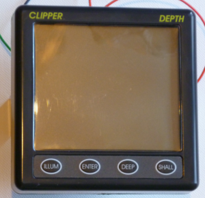
NASA Clipper Depth
- NASA Clipper Depth Echolot
Im Vergleich zu den meisten anderen Echoloten ist das Besondere des NASA Clipper Depth Echolots die Datenübertragung der Tiefendaten zu einem Tochterdisplay. Es wird dabei nicht ein standardisiertes Protokoll wie etwa NMEA-0183 oder ähnliches benutzt, sondern ein I2C Bus, der über ein Verbindungskabel direkt mit dem LCD-Treiber des Tochterdisplays kommuniziert. Diese Seite zeigt wie man die I2C-Daten dekodieren und in NMEA-0183 umwandeln kann.
Steckerbelegung
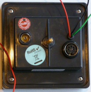
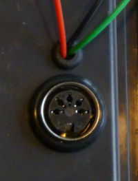
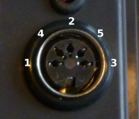
Der Datenausgang ist ein 5-poliger DIN-Stecker, siehe auch [[1]]. Das Aussehen des Steckers sowie die Nummerierung der Pins sind rechts dargestellt. Die Pinbelegung ist dabei folgende:
| Pin | Belegung |
|---|---|
| 1 | SCL (serial clock) |
| 2 | GND |
| 3 | SDA (serial data) |
| 4 | 12V |
| 5 | GND |
Datenübertragung
Die Leitungen SDA, SCL sind in dem Tochterdisplay mit einen Komparator (LM393) verbunden. Dieser wandelt die, durch die Abschlusswiderstände abgeschwächten Signale, wieder in 5V Signale um. Die Daten des LM393 werden an einen Microcontroller (PIC16F84A) gegeben, der diese an den LCD-Treiber (PCF8566P) weitergibt. Als Endanwender sind dabei zwei Dinge zu beachten:
- Wenn kein Tochterdisplay angeschlossen ist, sind die Ausgangsspannungen im Bereich 0-5V, es muss also kein Komparator benutzt werden.
- Das Echolot (der I2C Master) erwartet keinen Empfänger und sendet nach jedem Byte automatisch das ACK-Bit mit. Das Auslesen der Daten kann daher sowohl passiv als auch als ein normaler I2C slave stattfinden.
Datenformat
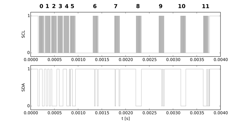
Jeder I2C Datensatz besteht aus 7 Adressbits, einem write bit (Byte 0) und 10 Datenbytes (Bytes 1-11). Die Datenbytes 1-5 bleiben konstant, die auszuwertenden Nutzdaten sind in den Bytes 7-11:
| Byte | 0 | 1 | 2 | 3 | 4 | 5 | 6 | 7 | 8 | 9 | 10 | 11 |
|---|---|---|---|---|---|---|---|---|---|---|---|---|
| Bedeutung | ADDR+WRITE | CMD | CMD | CMD | CMD | CMD | DATA | DATA | DATA | DATA | DATA | DATA |
| Inhalt | 0x3E+W = 0x7C | 0xCE | 0x80 | 0xE0 | 0xF8 | 0x70 | DATA | DATA | DATA | DATA | DATA | DATA |
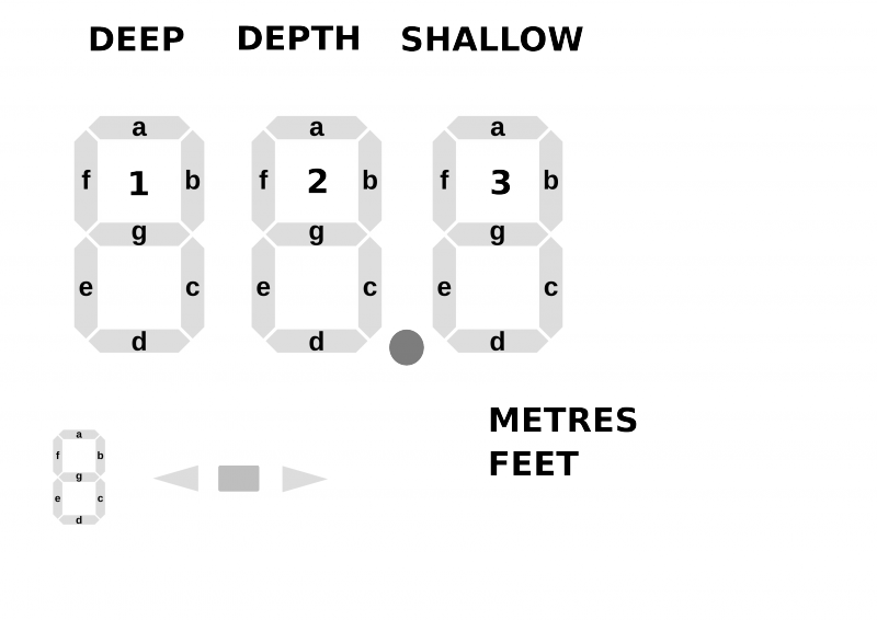
Jedes einzelne Bit in Bytes 7-11 repräsentiert dabei ein Segment der LCD:
| Byte | LCD Bit 7 | LCD Bit 6 | LCD Bit 5 | LCD Bit 4 | LCD Bit 3 | LCD Bit 2 | LCD Bit 1 | LCD Bit 0 |
|---|---|---|---|---|---|---|---|---|
| 6 | 2d | 2c | 2e | 2g | 2f | 2b | 2a | DEPTH |
| 7 | 3a | SHALLOW | 3f | 3b | 3e | 3g | 3d | 3c |
| 8 | N.A. | N.A. | N.A. | N.A. | N.A. | N.A. | N.A. | FEET |
| 9 | DEZ. Punkt | METRES | N.A. | N.A. | N.A. | N.A. | N.A. | N.A. |
| 10 | N.A. | PFEIL L | 1a | DEEP | 1f | 1b | 1e | 1g |
| 11 | 1d | 1c | N.A. | N.A. | N.A. | N.A. | BLOCK | Pfeil R |
Arduino Sketch
Der folgende Arduino Sketch zeigt wie man die Daten auslesen und in einen 0183 kompatiblen NMEA String konvertieren kann. Bitte beachten, dass der Sketch die Tiefeneinheit "m" und nicht "feet" annimmt!
/*

    NASAClipper_I2C_to_NMEA v0.5
    Decode the NASA Clipper Data into a NMEA compatible serial string


    written by Peter Holtermann
    with additions from Victor Klein


    This software is distributed under the GPL v3.0 License


    At the back of your NASA Clipper should be a round connector
    with 5 pins, looking roughly like this ASCII art:
      Pin Location          Pin Number
          |                     2
      \       /              4     5
    -           -          1         3

          O                     6

  Pin 1: SCL
  Pin 2: GND
  Pin 3: SDA
  Pin 4: 12V
  Pin 5: GND

  For Detail refer also to:

  http://wiki.openseamap.org/wiki/De:NASA_Clipper_Range

  If you connect SCL, SDA and GND with your arduino
  and upload this sketch you should get the depth
  information as serial data.

*/


#include <Wire.h>
const int ledPin =  13;      // the number of the LED pin

void setup()
{
  pinMode(ledPin, OUTPUT);
  Wire.begin(0x3e);
  Serial.begin(4800);
  Wire.onReceive(&myHandler);
  Serial.println("$HELLO SKIPPER! THIS IS NASACLIPPER I2C to NMEA v0.5!\n");
}

static bool FLAG_LED_ON = LOW;
static byte I2C_nrec;
char data_handler[11];
char data[11];
static byte FLAG_NEW_DATA = 0;
static bool FLAG_VALID_DATA = LOW;
static bool FLAG_DEPTH = LOW;
void myHandler(int numBytes)
{
  byte i=0;
  for(i=0;i<numBytes;i++)
  {
    data_handler[i] = Wire.read();
  }
  I2C_nrec = numBytes;
  FLAG_NEW_DATA = 1;
}


// The NASA Clipper sends a 12 byte I2C data packet, this data is directly send to a pcf8566p
// LCD Driver. The first byte is the address and the write direction, the next eleven bytes is data.
// The first 5 bytes is a command, the proceeding 6 bytes are data
// positions and contain the single LCD elements.
// Example data {0x7c,0xce,0x80,0xe0,0xf8,0x70,0x00,0x00,0x00,0x00,0x00,0x00};
//               addr   0    1    2    3    4    5    6    7    8    9    10
//                      com  com  com com   com dta  dta  dta  dta  dta  dta
// Example depth  : 23.3
// Digit number   : 12.3


char I2C_predata[5] =   {0xce,0x80,0xe0,0xf8,0x70};
char depth_mask[6] =    {0x01,0,0,0,0,0};
char decpoint_mask[6] = {0,0,0,0x80,0x0,0x0};
char metres_mask[6] =   {0,0,0,0x40,0x0,0x0};
char digit3_mask[6] =   {0,0xbf,0,0,0,0};
char digit3[10][6] = {                   // from https://en.wikipedia.org/wiki/Seven-segment_display
                   { 0, 0xbb,0,0,0,0  }, // zero, a,b,c,d,e,f,/g
                   { 0, 0x11, 0,0,0,0 }, // one /a,b,c,/d,/e,/f,/g
                   { 0, 0x9e, 0,0,0,0 }, // two a,b,/c,d,e,/f,g
                   { 0, 0x97, 0,0,0,0 }, // three a,b,c,d,/e,/f,g
                   { 0, 0x35, 0,0,0,0 }, // four /a,b,c,/d,/e,f,g
                   { 0, 0xa7, 0,0,0,0 }, // five a,/b,c,d,/e,f,g
                   { 0, 0xaf, 0,0,0,0 }, // six a,/b,c,d,e,f,g
                   { 0, 0x91, 0,0,0,0 }, // seven a,b,c,/d,/e,/f,/g
                   { 0, 0xbf, 0,0,0,0 }, // eight a,b,c,d,e,f,g
                   { 0, 0xb7, 0,0,0,0 }, // nine a,b,c,d,/e,f,g
                 };

char digit2_mask[6] = {0xfe,0,0,0,0,0};
char digit2[10][6] = {                   // from https://en.wikipedia.org/wiki/Seven-segment_display
                   { 0xee, 0, 0,0,0,0  },// zero, a,b,c,d,e,f,/g
                   { 0x44, 0, 0,0,0,0 }, // one /a,b,c,/d,/e,/f,/g
                   { 0xb6, 0, 0,0,0,0 }, // two a,b,/c,d,e,/f,g
                   { 0xd6, 0, 0,0,0,0 }, // three a,b,c,d,/e,/f,g
                   { 0x5c, 0, 0,0,0,0 }, // four /a,b,c,/d,/e,f,g
                   { 0xda, 0, 0,0,0,0 }, // five a,/b,c,d,/e,f,g
                   { 0xfa, 0, 0,0,0,0 }, // six a,/b,c,d,e,f,g
                   { 0x46, 0, 0,0,0,0 }, // seven a,b,c,/d,/e,/f,/g
                   { 0xfe, 0, 0,0,0,0 }, // eight a,b,c,d,e,f,g
                   { 0xde, 0, 0,0,0,0 }, // nine a,b,c,d,/e,f,g
                 };


char digit1_mask[6] = {0,0,0,0,0x2f,0xc0};
char digit1[10][6] = {                      // from https://en.wikipedia.org/wiki/Seven-segment_display
                   { 0, 0, 0,0,0x2e,0xc0 }, // zero, a,b,c,d,e,f,/g
                   { 0, 0, 0,0,0x04,0x40 }, // one /a,b,c,/d,/e,/f,/g
                   { 0, 0, 0,0,0x27,0x80 }, // two a,b,/c,d,e,/f,g
                   { 0, 0, 0,0,0x25,0xC0 }, // three a,b,c,d,/e,/f,g
                   { 0, 0, 0,0,0x0d,0x40 }, // four /a,b,c,/d,/e,f,g
                   { 0, 0, 0,0,0x29,0xC0 }, // five a,/b,c,d,/e,f,g
                   { 0, 0, 0,0,0x2b,0xC0 }, // six a,/b,c,d,e,f,g
                   { 0, 0, 0,0,0x24,0x40 }, // seven a,b,c,/d,/e,/f,/g
                   { 0, 0, 0,0,0x2f,0xc0 }, // eight a,b,c,d,e,f,g
                   { 0, 0, 0,0,0x2d,0xc0 }, // nine a,b,c,d,/e,f,g
                 };


void loop()
{
  byte i,j;
  byte digit_tmp0,digit_tmp1,dig1,dig2,dig3,dec_point,checksum;
  char dptstr[5],NMEADPTstr[20],cksstr[3],ind_dptstr;
  static char incomingByte,command[60], DEBUG_MODE=0;

  if(FLAG_NEW_DATA)
  {
    // DEBUG, stuff:
    //Serial.print("Got ");
    //Serial.print(I2C_nrec,DEC);
    //Serial.print(" bytes.\n");
    /*
    for(i=0;i<I2C_nrec;i++)
    {
      Serial.print(data_handler[i] & 0xFF, HEX);
      Serial.write('_');
    }
    Serial.print("\n");
    */

    // RAW I2C Data as a NMEA string.
    Serial.print("$IIDTA");
    for(i=0;i<I2C_nrec;i++)
    {
      Serial.print(",");
      Serial.print(data_handler[i] & 0xFF, DEC);
    }
    Serial.print("*\n");

    ind_dptstr = 0;

    // Copy the rawdata
    for(j=0;j<11;j++)
      {
        data[j] = data_handler[j];
        data_handler[j] = 0;
      }
    // Check if the first 5 byte (the command) are correct
    // They seem to stay always the same
    for(i=0;i<5;i++)
    {
      dptstr[i] = 0;

      if( (data[i] & 0xFF ) == (I2C_predata[i] & 0xFF) )
      {
        FLAG_VALID_DATA = HIGH;
      }
      else
      {
        FLAG_VALID_DATA = LOW;
        break;
      }
    }
    if((FLAG_VALID_DATA) & (I2C_nrec == 11))
    {
      // Decode the digits
      dig1 = 'N';
      dig2 = 'N';
      dig3 = 'N';
      dec_point = 'N';

       // DIGIT 3
      digit_tmp0 = data[6] & digit3_mask[1];
      for(i=0;i<10;i++)
      {
        if((digit3[i][1] & 0xFF) == (digit_tmp0 & 0xFF))
        {
          dig3 = '0' + i;
          break;
        }
      }
      // decimal point
      if((data[8] & decpoint_mask[3] & 0xFF) == (0x80))
      {
        dec_point = '.';
      }

      // We only consider data good, when the "DEPTH" symbol appears on the LCD
      if((data[5] & depth_mask[0] & 0xFF) == (0x01))
      {
        FLAG_DEPTH = HIGH;
      }
      else
      {
        FLAG_DEPTH = LOW;
      }


      // DIGIT 2
      digit_tmp0 = data[5] & digit2_mask[0];
      for(i=0;i<10;i++)
      {
        if((digit2[i][0] & 0xFF) == (digit_tmp0 & 0xFF))
        {
          dig2 = '0' + i;
          break;
        }
      }
      // DIGIT 1
      digit_tmp0 = data[9] & digit1_mask[4];
      digit_tmp1 = data[10] & digit1_mask[5];
      for(i=0;i<10;i++)
      {
        if(((digit1[i][4] & 0xFF) == (digit_tmp0 & 0xFF)) &
        ( (digit1[i][5] & 0xFF) == (digit_tmp1 & 0xFF)  ))
        {
          dig1 = '0' + i;
          break;
        }
      }

      i = 0;
      // Do we have good data? (FLAG_DEPTH and at least one digit
      if(((dig1 != 'N') | (dig2 != 'N') | (dig3 != 'N')) & (FLAG_DEPTH == HIGH))
        {
          ind_dptstr = 0;
          if(dig1 != 'N')
          {
            dptstr[ind_dptstr] = dig1;
            ind_dptstr ++;
          }
          if(dig2 != 'N')
          {
            dptstr[ind_dptstr] = dig2;
            ind_dptstr ++;
          }
          if(dec_point != 'N')
          {
            dptstr[ind_dptstr] = dec_point;
            ind_dptstr ++;
          }
          if(dig3 != 'N')
          {
            dptstr[ind_dptstr] = dig3;
            ind_dptstr ++;
          }
          dptstr[ind_dptstr] = '\0';
          strcpy(NMEADPTstr,"$IIDPT,");
          strcat(NMEADPTstr,dptstr);
          strcat(NMEADPTstr,",0.0*");
          // Calculate Checksum
          checksum = 0;
          i=0;

         while(1)
          {
            i++;
            if(NMEADPTstr[i] == '*')
              break;
            checksum = checksum ^ NMEADPTstr[i];
          }

          sprintf(cksstr,"%X",checksum & 0xFF);
          strcat(NMEADPTstr,cksstr);
          strcat(NMEADPTstr,"\r\n");
          if(FLAG_DEPTH == HIGH)
          {
            Serial.print(NMEADPTstr);
          }
          // Toggle the LED
          if( FLAG_LED_ON == HIGH) {
            FLAG_LED_ON = LOW;
            digitalWrite(ledPin, LOW);
            }
          else {
            FLAG_LED_ON = HIGH;
            digitalWrite(ledPin, HIGH);
            }
        }
      else
        {
          Serial.println("$bad data");
        }
    }
    // Get rid of old data
    for(i=0;i<11;i++)
    {
       data[i] = 0;
    }
    FLAG_NEW_DATA = 0;
  }

}
Funktionierendes Arduino Beispiel
Hier ein Beispiel für eine funktionierende Konfiguration die den Arduino Sketch verwendet. Die Bilder unten zeigen die Pinbelegung eines DIN-A/V-Kabel von Reichelt. ACHTUNG: Die Farbkodierung muss bei jedem Kabel neu bestimmt werden! Es besteht keine Garantie, dass diese gleichbleibt!
Steckerbelegung, Farbkodierung und NASA Clipper Range Pins des DIN-A/V-Kabels
