OpenSeaMap-dev:HW-logger/OSeaM-Manual(en): Unterschied zwischen den Versionen
Markus (Diskussion | Beiträge) (→Operating LEDs) |
Markus (Diskussion | Beiträge) |
||
| (27 dazwischenliegende Versionen von 2 Benutzern werden nicht angezeigt) | |||
| Zeile 8: | Zeile 8: | ||
|} | |} | ||
| + | [[Datei:OpenSeaMap-Logger-NMEA-0183-PS.jpg|thumb|300px|NMEA-0183 Logger]] | ||
| + | __TOC__ | ||
| + | |||
| + | |||
| + | {| frame="box" bgcolor="#7fff00" cellpadding="6" | ||
| + | | Actual Firmware for '''2x NMEA''': [http://wkla.no-ip.biz/ArduinoWiki/doku.php?id=arduino:oseam:firmware V0.1.12] | ||
| + | |} | ||
| − | [ | + | |
| + | {| frame="box" bgcolor="#7fff00" cellpadding="6" | ||
| + | | Actual Firmware for '''Seatalk''': [http://wkla.no-ip.biz/ArduinoWiki/doku.php?id=arduino:oseam:firmware V0.1.15] | ||
| + | |} | ||
| + | |||
| + | Developer pagee: http://wkla.no-ip.biz/ArduinoWiki/doku.php?id=arduino:oseam (German) | ||
== Preface == | == Preface == | ||
[[File:4 GB SDHC Card.JPG|right|100px]] | [[File:4 GB SDHC Card.JPG|right|100px]] | ||
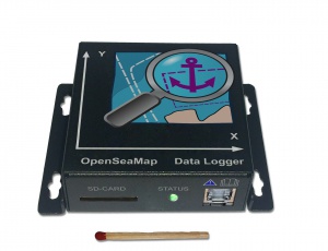
| − | The OpenSeaMap data logger is capable | + | The OpenSeaMap data logger is capable of logging data of '''two NMEA-0183 devices''', for example depth-sounder and GPS. For this, there are two input channels. Both inputs will be written with a timestamp for a later chronological sorting. Data about acceleration and displacement will also be logged to determine heeling, heaving and pitching. All data will be written to an SD-card. Data is recorded raw for further processing, no filtering is done. |
; Features | ; Features | ||
| − | * Data logger for NMEA- | + | * Data logger for NMEA-data |
| − | * | + | * Built-in 6-axis MotionTracking (Gyroscope and Accelerometer) |
| − | * | + | * Writing data on standard SD-card in NMEA-0183 format |
| − | * | + | * Simplest handling |
| − | * LED for operation, input data and | + | * LED for operation, input data, and SD-card access |
| − | * 2 | + | * 2 NMEA-0183 inputs (4800 Baud) |
| − | * 1 | + | * 1 Seatalk-1 input alternatively (selectable by internal jumper) |
| − | * | + | * 12 V supply |
== Delivery == | == Delivery == | ||
| Zeile 41: | Zeile 53: | ||
== Installation == | == Installation == | ||
| − | === Mounting the | + | === Mounting the Logger === |
| − | Install the logger to a protected location where you have access to the SD card and you can see the | + | Install the logger to a protected location where you have access to the SD-card and where you can see the LEDs. |
| − | Mount it as perpendicular as possible to the front panel of the navigation area (outside or inside) or perpendicular to a vertical wall behind. The top edge ideally will be horizontally to the ship's transverse axis. The two arrows on the upper surface indicate the direction in respect to the ship's axis. | + | Mount it as perpendicular as possible to the front panel of the navigation area (outside or inside) or perpendicular to a vertical wall behind. The top edge ideally will be horizontally to the ship's transverse axis. The two arrows on the upper surface indicate the direction in respect to the ship's axis. Please describe this in the metadata of your ship. |
=== Connecting the Cable === | === Connecting the Cable === | ||
| − | The logger will turn on automatically with the operating voltage. After switching on it takes about 30 seconds the logger starts to write data. If the green power indicator LED is lighting, the logger is active and ready to receive. The connection is made via the RJ45 jack. This is where all signals and the supply are connected. | + | The logger will turn on automatically with the operating voltage. After switching on, it takes about 30 seconds until the logger starts to write data. If the green power indicator LED is lighting, the logger is active and ready to receive. The connection is made via the RJ45-jack. This is where all signals and the supply are connected. |
| − | A | + | A suitable cable comes with the logger. In case that you need to buy a longer one, please use a simple normal '''patch cable''' (network cable) as it is available at any electronics store. Make sure that this is ''not'' a "crossover" cable" or "cross cable" for directly connecting two computers. |
| − | + | Cut the patch cable, you need one side (connector and open end). The colors show you if the cable is European or American. If the outer wires in the tranparent plugs are green, you've got a cable according to the European standard (568A), if these are orange it is an American standard cable (568B). | |
There are the following connections: | There are the following connections: | ||
| − | [[File:Rj45plug-8p8c.png| | + | {| |
| + | | [[File:Rj45plug-8p8c.png|thumb|Plug]] | ||
| + | | [[File:Stecker RJ45 568B Pfeil.jpg|thumb|American patch-cable. <br> The outer wires are orange.]] | ||
| + | | [[File:Utp_diy02_sequenceInCable.jpg|thumb|Conductor pairs]] | ||
| + | |} | ||
| + | <div style="clear:both;"> | ||
{| class="wikitable float-right" | {| class="wikitable float-right" | ||
|- class="hintergrundfarbe6" | |- class="hintergrundfarbe6" | ||
| − | ! Pin !! -568A pairno. !! -568B pairno. !! -568A color !! -568B (AT&T 258A) color !! Logger meaning | + | ! Pin !! -568A pairno. !! -568B pairno. !! -568A color <br> (Europ. cable) !! -568B (AT&T 258A) color <br> (American cable) !! Logger meaning |
|- | |- | ||
! 1 | ! 1 | ||
| 3 || 2 | | 3 || 2 | ||
|[[Datei:Wire white green stripe.svg|60px|Pair 3 Tip]] white/green line | |[[Datei:Wire white green stripe.svg|60px|Pair 3 Tip]] white/green line | ||
| − | |[[Datei:Wire white orange stripe.svg|60px|Pair 2 Tip]] white/ | + | |[[Datei:Wire white orange stripe.svg|60px|Pair 2 Tip]] white/orange line |
| Seatalk - | | Seatalk - | ||
|- | |- | ||
| Zeile 76: | Zeile 93: | ||
|[[Datei:Wire white orange stripe.svg|60px|Pair 2 Tip]] white/orange line | |[[Datei:Wire white orange stripe.svg|60px|Pair 2 Tip]] white/orange line | ||
|[[Datei:Wire white green stripe.svg|60px|Pair 3 Tip]] white/green line | |[[Datei:Wire white green stripe.svg|60px|Pair 3 Tip]] white/green line | ||
| − | | NMEA | + | | NMEA B - |
|- | |- | ||
! 4 | ! 4 | ||
| Zeile 82: | Zeile 99: | ||
|[[Datei:Wire blue white stripe.svg|60px|Pair 1 Ring]] blue/white line or blue | |[[Datei:Wire blue white stripe.svg|60px|Pair 1 Ring]] blue/white line or blue | ||
|[[Datei:Wire blue white stripe.svg|60px|Pair 1 Ring]] blue/white line or blue | |[[Datei:Wire blue white stripe.svg|60px|Pair 1 Ring]] blue/white line or blue | ||
| − | | NMEA | + | | NMEA A + |
|- | |- | ||
! 5 | ! 5 | ||
| Zeile 88: | Zeile 105: | ||
|[[Datei:Wire white blue stripe.svg|60px|Pair 1 Tip]] white/blue line | |[[Datei:Wire white blue stripe.svg|60px|Pair 1 Tip]] white/blue line | ||
|[[Datei:Wire white blue stripe.svg|60px|Pair 1 Tip]] white/blue line | |[[Datei:Wire white blue stripe.svg|60px|Pair 1 Tip]] white/blue line | ||
| − | | NMEA | + | | NMEA A - |
|- | |- | ||
! 6 | ! 6 | ||
| Zeile 94: | Zeile 111: | ||
|[[Datei:Wire orange white stripe.svg|60px|Pair 2 Ring]] orange/white line or orange | |[[Datei:Wire orange white stripe.svg|60px|Pair 2 Ring]] orange/white line or orange | ||
|[[Datei:Wire green white stripe.svg|60px|Pair 3 Ring]] green/white line or green | |[[Datei:Wire green white stripe.svg|60px|Pair 3 Ring]] green/white line or green | ||
| − | | NMEA | + | | NMEA B + |
|- | |- | ||
! 7 | ! 7 | ||
| Zeile 110: | Zeile 127: | ||
<div style="clear:both;"></div> | <div style="clear:both;"></div> | ||
| − | === Connecting the Sounder === | + | CAUTION: In the printed manual channel A and B are interchanged. |
| + | |||
| + | === Connecting the Sounder NMEA === | ||
Connect the NMEA output of the sounder/sonar to the NMEA input of the logger. | Connect the NMEA output of the sounder/sonar to the NMEA input of the logger. | ||
<br> Use the NMEA-A for the sounder/sonar if possible. | <br> Use the NMEA-A for the sounder/sonar if possible. | ||
| Zeile 124: | Zeile 143: | ||
|} | |} | ||
| − | If the Sounder works with Satalk-1, | + | If the Sounder works with Satalk-1, see [[#Connecting Seatalk|switch port A from NMEA-0183 to Seatalk-1]]. |
| + | |||
| + | === Connecting Sounder Seatalk === | ||
| + | Connect the Seatalk-1 output of the sonar to the Seatalk-1 input of the logger. | ||
| + | |||
| + | {| style="float:right" | ||
| + | | [[File:OpenSeaMap-Data-logger circuit-board_NMEA.jpg|thumb|Jumper for NMEA (default)]] | ||
| + | | [[File:OpenSeaMap-Data-logger circuit-board_SeaTalk.jpg|thumb|Jumper for Seatalk]] | ||
| + | |} | ||
| + | |||
| + | {| class="wikitable" | ||
| + | ! Signal Sonar || Seatalk | ||
| + | |- | ||
| + | ! - | ||
| + | | Pin 1 | ||
| + | |- | ||
| + | ! + | ||
| + | | Pin 2 | ||
| + | |} | ||
| − | === Connecting GPS === | + | The input A has to be switched electrically from NMEA-0183 to Seatalk-1. |
| + | |||
| + | For this, there are two steps necessary: | ||
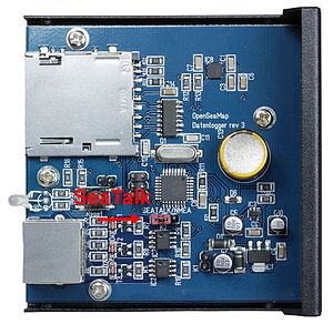
| + | # Open the logger. There is a red jumper in the middle of the board. On the board you will find the words "Seatalk/NMEA". For Seatalk, put the bridge on the left and the middle pin (where "Seatalk" is written). For NMEA, put the bridge on the right and the middle pin (where "NMEA" is written). | ||
| + | # Start the [[#Firmwareupdate with SD-card|configuration program]] and create a configuration file with the appropriate entries. Save this configuration file on an SD-card and start the logger with this card. | ||
| + | |||
| + | === Connecting GPS NMEA === | ||
Connect the NMEA output of the GPS device to the NMEA input of the logger. | Connect the NMEA output of the GPS device to the NMEA input of the logger. | ||
<br>Use the NMEA B for the GPS if possible. | <br>Use the NMEA B for the GPS if possible. | ||
| Zeile 140: | Zeile 183: | ||
|} | |} | ||
| − | === Connecting | + | === Connecting Supply (12 V) === |
| − | + | The logger is operating with 12 V voltage (9-15V). To start the data recording automatically when the navigation devices are turned on, the logger must be connected to the same circuit as the navigation instruments. | |
| − | |||
| − | |||
| − | |||
| − | |||
| − | |||
| − | The logger is operating with | ||
{| class="wikitable" | {| class="wikitable" | ||
| Zeile 160: | Zeile 197: | ||
=== Connecting Cable === | === Connecting Cable === | ||
| − | + | Terminal strips are ideal. If you connect the cable to a terminal block, you can bend the stripped end, in order to fix it better in the terminal block. | |
| − | === Strain | + | === Strain Relief === |
| − | The loose end of the cable must be secured with a strain relief when connected to the onboard electronics (the wires are very thin). | + | The loose end of the cable must be secured with a strain relief when connected to the onboard electronics (the wires are very thin). |
== Functions == | == Functions == | ||
| − | After applying the operating voltage and a short initialization time (30 seconds), the data is written automatically to the SD card. | + | After applying the operating voltage and a short initialization time (30 seconds), the data is written automatically to the SD-card. |
| − | === Control | + | === Control Panel === |
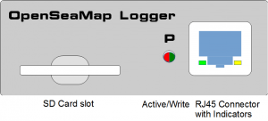
The control panel is self-explaining: | The control panel is self-explaining: | ||
| Zeile 175: | Zeile 212: | ||
{| class="wikitable" | {| class="wikitable" | ||
| − | ! SD card | + | ! SD-card |
| − | | Insert SD card | + | | Insert SD-card |
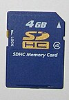
| − | | We recommend a | + | | We recommend a 4 GB SD-card. It can record up to 40 days. The SD-card must be formatted FAT-32. |
|- | |- | ||
! Active/write | ! Active/write | ||
| <span style="background-color: green;"> </span> Green <br><span style="background-color: red;"> </span> Red flashing | | <span style="background-color: green;"> </span> Green <br><span style="background-color: red;"> </span> Red flashing | ||
| − | | | + | | The logger is active and ready to receive <br> the logger writes to the SD-card. |
|- | |- | ||
| − | ! RJ45 Connector | + | ! RJ45-Connector |
| − | | Connect power supply <br> | + | | Connect power supply <br> Connect sonar <br> Connect GPS <br> <br> <span style="background-color: yellow;"> </span> <span style="background-color: green;"> </span> Gelb/Green flashing |
| − | | <br> <br> <br> <br> | + | | <br> <br> <br> <br> On the NMEA channel, a valid signal is received. |
|} | |} | ||
| − | Insert the SD card '''before turning on'''. | + | Insert the SD-card '''before turning on''' the logger. |
| − | <br> Remove the SD card from the logger only when the | + | <br> Remove the SD-card from the logger only when the logger is '''turned off'''. |
| − | On every start and every hour a new file | + | On every start and every hour, a new file will be created automatically on the SD-card. |
=== Errors === | === Errors === | ||
| − | + | If an error of writing the data occurs during start or operation of the logger, the red LED flash regularly every second: | |
{| class="wikitable" | {| class="wikitable" | ||
| Zeile 201: | Zeile 238: | ||
| LED next to plug | | LED next to plug | ||
| <span style="background-color: red;"> </span> Red flashing | | <span style="background-color: red;"> </span> Red flashing | ||
| − | | SD-card is full | + | | SD-card is full. |
| − | | | + | | Replace SD-card with an empty one. |
|} | |} | ||
Other possible causes: | Other possible causes: | ||
| − | * SD card has an unsupported file format (for data cards there is only | + | * SD-card has an unsupported file format (for data cards there is only FAT-16 and FAT-32 supported) |
| − | * SD card is not writable or is not recognized. Please test the card on your PC. | + | * SD-card is not writable or is not recognized. Please test the card on your PC. |
=== Operating LEDs === | === Operating LEDs === | ||
| Zeile 215: | Zeile 252: | ||
| LED next to plug <br>LED 1 in plug <br>LED 2 in plug | | LED next to plug <br>LED 1 in plug <br>LED 2 in plug | ||
| <span style="background-color: green;"> </span> Green <br> off <br> off | | <span style="background-color: green;"> </span> Green <br> off <br> off | ||
| − | | The logger is active and reciving <br> <br> | + | | The logger is active and reciving. <br> <br> |
|- | |- | ||
| LED next to plug <br>LED 1 in plug <br>LED 2 in plug | | LED next to plug <br>LED 1 in plug <br>LED 2 in plug | ||
| Zeile 226: | Zeile 263: | ||
|- | |- | ||
| LED next to plug <br>LED 1 in plug <br>LED 2 in plug | | LED next to plug <br>LED 1 in plug <br>LED 2 in plug | ||
| − | | <span style="background-color: red;"> </span> Red | + | | <span style="background-color: red;"> </span> Red flickering <br> <br> |
| − | | The logger is writing data on the SD card. <br> <br> | + | | The logger is writing data on the SD-card. <br> <br> |
|- | |- | ||
| LED next to plug <br> LED 1 in plug <br> LED 2 in plug | | LED next to plug <br> LED 1 in plug <br> LED 2 in plug | ||
| − | | <br> <span style="background-color: yellow;"> </span> Yellow | + | | <br> <span style="background-color: yellow;"> </span> Yellow flickering <br> <span style="background-color: green;"> </span> Green flickering |
| − | | <br> | + | | <br> In this NMEA channel, a valid signal is received. <br> In this NMEA channel, a valid signal is received. |
|} | |} | ||
| − | === Preparing the SD card === | + | === Preparing the SD-card === |
| − | We recommend a ''' | + | We recommend a '''4 GB SD-card.''' It can record up to 40 days. (about 4 MB per hour, 100 MB per day). The SD-card must be formatted '''FAT-32'''. |
| − | === Firmwareupdate with SD card === | + | === Firmwareupdate with SD-card === |
| − | A SD card with '''FAT 16 file system''' must be used for the firmware update. The easiest way is to use a SD card with '''2 GB''' or smaller. This can be simply formatted with FAT 16 (on some operation systems are also just plain FAT) or creating a small partition. The latest firmware file can be downloaded, and put on the root of the SD card. | + | A SD-card with '''FAT-16 file system''' must be used for the firmware update. The easiest way is to use a SD-card with '''2 GB''' or smaller. This can be simply formatted with FAT-16 (on some operation systems are also just plain FAT) or creating a small partition. The latest firmware file can be downloaded, and put on the root of the SD-card. |
A software tool that simplifies the update process is in progress. | A software tool that simplifies the update process is in progress. | ||
| Zeile 249: | Zeile 286: | ||
== Programm "OpenSeaMap-Logger" == | == Programm "OpenSeaMap-Logger" == | ||
| − | Mit dem Programm [http:// " | + | Mit dem Programm [http://wkla.no-ip.biz/downloader/download.php?ID=64 "MCS Depth-Logger"] kann man Tiefen-Daten hochladen und den Logger konfigurieren: |
| − | # Daten | + | # Verwaltung/Backup/Restore der SD Karten |
| − | # | + | # Verwaltung der Firmware inkl. Vorbereitung der SD Karte für ein evt. Firmware Update |
| − | ## | + | # Überprüfung/Korrektur der geloggten Daten |
| − | ## | + | # Export ins NMEA Format |
| − | ## | + | # Upload auf einen Server |
| − | ## | + | # Darstellung einzelner Daten auf Karten |
| − | ## | + | # Verwaltung von Routen |
| − | ## | + | ## Hinzufügen/Löschen von einzelnen Dateien |
| − | # | + | ## Darstellung auf Karte |
| − | + | # Kartendarstellung | |
| − | + | ## verschiedene Kartenprovider: OpenStreetMap, OpenSeaMap, Virtual Earth | |
| + | ## Möglichkeit verschiedener Overlays wie Sportstätten, Seezeichen | ||
| + | ## Darstellung verschiedener Daten als Diagramm: Tiefe, Höhe, Beschleuningung und Lage, Geschwindigkeit | ||
| + | # Internationalisierung: Sprachen Deutsch und Englisch, Maßsysteme: metrisch, imprial, nautisch | ||
| + | |||
| + | [http://wkla.no-ip.biz/ArduinoWiki/doku.php?id=arduino:oseam:config Manual for "MCS Depth Logger"] | ||
== Operation == | == Operation == | ||
| Zeile 275: | Zeile 317: | ||
| − | ; SD card | + | ; SD-card |
| − | : On an SD card with 2 GB can be recorded for about 18 days. <br> Approximately | + | : On an SD-card with 2 GB can be recorded for about 18 days. <br> Approximately 100 MB of data recorded per day. <br> (This can of course vary according to the GPS and sonar used.) |
| − | : Thus, the SD card needs to be replaced in time. | + | : Thus, the SD-card needs to be replaced in time. |
| − | === For | + | === For Charter Combapies === |
| − | For simple handling, use 2 SD | + | For simple handling, use 2 SD-cards to each device. |
| − | : After each charter trip the SD card needs to be replaced. | + | : After each charter trip the SD-card needs to be replaced. |
| − | : To do this, | + | : To do this, label for each vessel 2 SD-cards with the ship's name. <br> One card is plugged into the logger, the other comes into the office to vessel/charter-documents. |
| − | : The logger automatically starts with the navigation device. <br> The charter customers need to worry about anything. | + | : The logger automatically starts with the navigation device. <br> The charter customers don't need to worry about anything. |
| − | |||
| − | |||
| + | The following check lists can be adapted to your charter base: | ||
; When crew changes | ; When crew changes | ||
| − | # | + | # Remove the written SD-card |
| − | # | + | # Insert new empty card (from the vessel documents) |
| − | # | + | # Bring removed card with the ship's documentation to the office |
| Zeile 308: | Zeile 349: | ||
# put removed card into a PC and [[#Daten hochladen|upload data to the server]]. | # put removed card into a PC and [[#Daten hochladen|upload data to the server]]. | ||
# assign the uploaded data to the correct ship (choose from the list of vessels) | # assign the uploaded data to the correct ship (choose from the list of vessels) | ||
| − | # Erase data on the described card, <br> put empty card to the shipping documents. | + | # Erase data on the described card, <br> put the empty card to the shipping documents. |
| − | # Note in the ship's documentation: <br> Data uploaded <trip/customer> <date> <br> Data deleted <trip/customer> <date> | + | # Note in the ship's documentation: <br> Data uploaded <trip/customer> <date> <br> Data deleted <trip/customer> <date> |
| − | |||
== Meta data == | == Meta data == | ||
| Zeile 318: | Zeile 358: | ||
== Uploading data == | == Uploading data == | ||
| − | # You need a computer with Internet connection and SD card reader | + | # You need a computer with Internet connection and SD-card reader |
| − | # Put the SD card into the SD card slot | + | # Put the SD card into the SD-card slot |
# Please log in using your username: [http://depth.openseamap.org http://depth.openseamap.org] | # Please log in using your username: [http://depth.openseamap.org http://depth.openseamap.org] | ||
# Enter the metadata of your ship and to the measuring device. <br> If you use the same ship as the last time, and if nothing was changed in the measuring device, you can simply select your ship from the list of your ships. | # Enter the metadata of your ship and to the measuring device. <br> If you use the same ship as the last time, and if nothing was changed in the measuring device, you can simply select your ship from the list of your ships. | ||
# Upload the data to the server | # Upload the data to the server | ||
| + | |||
| + | == Credits == | ||
| + | OpenSeaMap says thanks to: | ||
| + | |||
| + | ; Wilfried Klaas | ||
| + | : for developing the hard- and software | ||
| + | |||
| + | ; KoBo Trading Company Limited, HongKong | ||
| + | : for prefinancing | ||
| + | |||
| + | ; KoBo (Shenzhen) electronics company Limited, Shenzhen, China | ||
| + | : for prototyping and production | ||
| + | |||
| + | ; AK Modulbus GmbH | ||
| + | : for distribution, but AK Modulbus can not spend any technical support for the logger. | ||
| + | |||
| + | ; Küstenschmiede | ||
| + | : for Logger distribution: [https://shop4gis.com shop4gis.com] | ||
Aktuelle Version vom 6. Juni 2018, 08:52 Uhr
| Sprachen: | Deutsch | English |
|---|
Inhaltsverzeichnis
| Actual Firmware for 2x NMEA: V0.1.12 |
| Actual Firmware for Seatalk: V0.1.15 |
Developer pagee: http://wkla.no-ip.biz/ArduinoWiki/doku.php?id=arduino:oseam (German)
Preface
The OpenSeaMap data logger is capable of logging data of two NMEA-0183 devices, for example depth-sounder and GPS. For this, there are two input channels. Both inputs will be written with a timestamp for a later chronological sorting. Data about acceleration and displacement will also be logged to determine heeling, heaving and pitching. All data will be written to an SD-card. Data is recorded raw for further processing, no filtering is done.
- Features
- Data logger for NMEA-data
- Built-in 6-axis MotionTracking (Gyroscope and Accelerometer)
- Writing data on standard SD-card in NMEA-0183 format
- Simplest handling
- LED for operation, input data, and SD-card access
- 2 NMEA-0183 inputs (4800 Baud)
- 1 Seatalk-1 input alternatively (selectable by internal jumper)
- 12 V supply
Delivery
You can order the NMEA-Logger here.
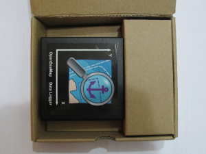
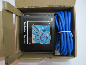
It comes to you in a small packet.
- Content
- 1 NMEA-Logger
- 1 Cable with RJ45 jack and open end
- Manual in English and German
Installation
Mounting the Logger
Install the logger to a protected location where you have access to the SD-card and where you can see the LEDs.
Mount it as perpendicular as possible to the front panel of the navigation area (outside or inside) or perpendicular to a vertical wall behind. The top edge ideally will be horizontally to the ship's transverse axis. The two arrows on the upper surface indicate the direction in respect to the ship's axis. Please describe this in the metadata of your ship.
Connecting the Cable
The logger will turn on automatically with the operating voltage. After switching on, it takes about 30 seconds until the logger starts to write data. If the green power indicator LED is lighting, the logger is active and ready to receive. The connection is made via the RJ45-jack. This is where all signals and the supply are connected.
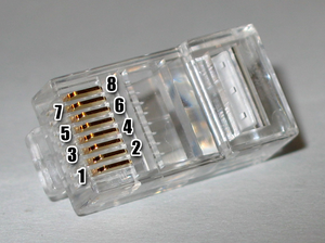
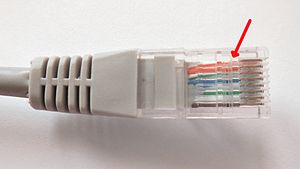
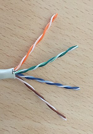
A suitable cable comes with the logger. In case that you need to buy a longer one, please use a simple normal patch cable (network cable) as it is available at any electronics store. Make sure that this is not a "crossover" cable" or "cross cable" for directly connecting two computers. Cut the patch cable, you need one side (connector and open end). The colors show you if the cable is European or American. If the outer wires in the tranparent plugs are green, you've got a cable according to the European standard (568A), if these are orange it is an American standard cable (568B).
There are the following connections:
CAUTION: In the printed manual channel A and B are interchanged.
Connecting the Sounder NMEA
Connect the NMEA output of the sounder/sonar to the NMEA input of the logger.
Use the NMEA-A for the sounder/sonar if possible.
| Signal Sonar | NMEA-A |
|---|---|
| - | Pin 5 |
| + | Pin 4 |
If the Sounder works with Satalk-1, see switch port A from NMEA-0183 to Seatalk-1.
Connecting Sounder Seatalk
Connect the Seatalk-1 output of the sonar to the Seatalk-1 input of the logger.
| Signal Sonar | Seatalk |
|---|---|
| - | Pin 1 |
| + | Pin 2 |
The input A has to be switched electrically from NMEA-0183 to Seatalk-1.
For this, there are two steps necessary:
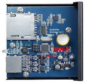
- Open the logger. There is a red jumper in the middle of the board. On the board you will find the words "Seatalk/NMEA". For Seatalk, put the bridge on the left and the middle pin (where "Seatalk" is written). For NMEA, put the bridge on the right and the middle pin (where "NMEA" is written).
- Start the configuration program and create a configuration file with the appropriate entries. Save this configuration file on an SD-card and start the logger with this card.
Connecting GPS NMEA
Connect the NMEA output of the GPS device to the NMEA input of the logger.
Use the NMEA B for the GPS if possible.
| Signal GPS | NMEA-B |
|---|---|
| - | Pin 3 |
| + | Pin 6 |
Connecting Supply (12 V)
The logger is operating with 12 V voltage (9-15V). To start the data recording automatically when the navigation devices are turned on, the logger must be connected to the same circuit as the navigation instruments.
| Supply | Cable | Color |
|---|---|---|
| GND | Pin 7 | |
| +12 V | Pin 8 |
Connecting Cable
Terminal strips are ideal. If you connect the cable to a terminal block, you can bend the stripped end, in order to fix it better in the terminal block.
Strain Relief
The loose end of the cable must be secured with a strain relief when connected to the onboard electronics (the wires are very thin).
Functions
After applying the operating voltage and a short initialization time (30 seconds), the data is written automatically to the SD-card.
Control Panel
The control panel is self-explaining:
| SD-card | Insert SD-card | We recommend a 4 GB SD-card. It can record up to 40 days. The SD-card must be formatted FAT-32. |
|---|---|---|
| Active/write | Green Red flashing |
The logger is active and ready to receive the logger writes to the SD-card. |
| RJ45-Connector | Connect power supply Connect sonar Connect GPS Gelb/Green flashing |
On the NMEA channel, a valid signal is received. |
Insert the SD-card before turning on the logger.
Remove the SD-card from the logger only when the logger is turned off.
On every start and every hour, a new file will be created automatically on the SD-card.
Errors
If an error of writing the data occurs during start or operation of the logger, the red LED flash regularly every second:
| Where | What | Meaning | Action |
|---|---|---|---|
| LED next to plug | Red flashing | SD-card is full. | Replace SD-card with an empty one. |
Other possible causes:
- SD-card has an unsupported file format (for data cards there is only FAT-16 and FAT-32 supported)
- SD-card is not writable or is not recognized. Please test the card on your PC.
Operating LEDs
| Where | What | Meaning |
|---|---|---|
| LED next to plug LED 1 in plug LED 2 in plug |
Green off off |
The logger is active and reciving. |
| LED next to plug LED 1 in plug LED 2 in plug |
Green flashing |
Initialization of the logger (about 30 sec) |
| LED next to plug LED 1 in plug LED 2 in plug |
Red |
The logger is currently turning off. |
| LED next to plug LED 1 in plug LED 2 in plug |
Red flickering |
The logger is writing data on the SD-card. |
| LED next to plug LED 1 in plug LED 2 in plug |
Yellow flickering Green flickering |
In this NMEA channel, a valid signal is received. In this NMEA channel, a valid signal is received. |
Preparing the SD-card
We recommend a 4 GB SD-card. It can record up to 40 days. (about 4 MB per hour, 100 MB per day). The SD-card must be formatted FAT-32.
Firmwareupdate with SD-card
A SD-card with FAT-16 file system must be used for the firmware update. The easiest way is to use a SD-card with 2 GB or smaller. This can be simply formatted with FAT-16 (on some operation systems are also just plain FAT) or creating a small partition. The latest firmware file can be downloaded, and put on the root of the SD-card.
A software tool that simplifies the update process is in progress.
| Firmware-Version | Date |
|---|---|
| xxx | yyy |
Programm "OpenSeaMap-Logger"
Mit dem Programm "MCS Depth-Logger" kann man Tiefen-Daten hochladen und den Logger konfigurieren:
- Verwaltung/Backup/Restore der SD Karten
- Verwaltung der Firmware inkl. Vorbereitung der SD Karte für ein evt. Firmware Update
- Überprüfung/Korrektur der geloggten Daten
- Export ins NMEA Format
- Upload auf einen Server
- Darstellung einzelner Daten auf Karten
- Verwaltung von Routen
- Hinzufügen/Löschen von einzelnen Dateien
- Darstellung auf Karte
- Kartendarstellung
- verschiedene Kartenprovider: OpenStreetMap, OpenSeaMap, Virtual Earth
- Möglichkeit verschiedener Overlays wie Sportstätten, Seezeichen
- Darstellung verschiedener Daten als Diagramm: Tiefe, Höhe, Beschleuningung und Lage, Geschwindigkeit
- Internationalisierung: Sprachen Deutsch und Englisch, Maßsysteme: metrisch, imprial, nautisch
Operation
For the skipper
- Start
- If the logger is connected to the power supply of Navigation Devices,
it starts automatically when the navigation devices are turned on.
- If the navigation devices be turned off (or if a power interruption),
the log file is automatically closed.
- Once the power supply is switched on again, a new file is created automatically.
- The logger has an built-in power-backup-circuit
ensuring there is no data write fault during interruption of the supply voltage.
- SD-card
- On an SD-card with 2 GB can be recorded for about 18 days.
Approximately 100 MB of data recorded per day.
(This can of course vary according to the GPS and sonar used.)
- Thus, the SD-card needs to be replaced in time.
For Charter Combapies
For simple handling, use 2 SD-cards to each device.
- After each charter trip the SD-card needs to be replaced.
- To do this, label for each vessel 2 SD-cards with the ship's name.
One card is plugged into the logger, the other comes into the office to vessel/charter-documents.
- The logger automatically starts with the navigation device.
The charter customers don't need to worry about anything.
The following check lists can be adapted to your charter base:
- When crew changes
- Remove the written SD-card
- Insert new empty card (from the vessel documents)
- Bring removed card with the ship's documentation to the office
- During crew briefing
- It would be nice if the charterers employee in charge briefly tells that the charter company participates in the project "Detection of shallow water depths". And that the skipper can support the project particularly well by selectively moves a bit in bays and harbor entrances back and forth to capture the depth of the key points well.
- This could also be advertised on your website.
- In the office
- put removed card into a PC and upload data to the server.
- assign the uploaded data to the correct ship (choose from the list of vessels)
- Erase data on the described card,
put the empty card to the shipping documents. - Note in the ship's documentation:
Data uploaded <trip/customer> <date>
Data deleted <trip/customer> <date>
Meta data
For a reliable evaluation, we need accurate information about the ship and the measuring device used.
These data need be entered only once per vessel and are then valid for all log files for this ship. Changes to marine electronics, the original data can be easily changed or expanded.
Uploading data
- You need a computer with Internet connection and SD-card reader
- Put the SD card into the SD-card slot
- Please log in using your username: http://depth.openseamap.org
- Enter the metadata of your ship and to the measuring device.
If you use the same ship as the last time, and if nothing was changed in the measuring device, you can simply select your ship from the list of your ships. - Upload the data to the server
Credits
OpenSeaMap says thanks to:
- Wilfried Klaas
- for developing the hard- and software
- KoBo Trading Company Limited, HongKong
- for prefinancing
- KoBo (Shenzhen) electronics company Limited, Shenzhen, China
- for prototyping and production
- AK Modulbus GmbH
- for distribution, but AK Modulbus can not spend any technical support for the logger.
- Küstenschmiede
- for Logger distribution: shop4gis.com
